Abstract

- 3 main stages, Fetch, Decode & Execute
- Thew 2 main Register involved are the Instruction Register and the address register (Program Counter)
Wasted computation
Each pipeline stage is isolated and independent from each other. When one stage is running, the other stages will be idle. You can see from the animation above, when the Instruction is decoded, the instruction register is actually ready to take in the next instruction.
This can be optimised with Instruction-Level Parallelism.
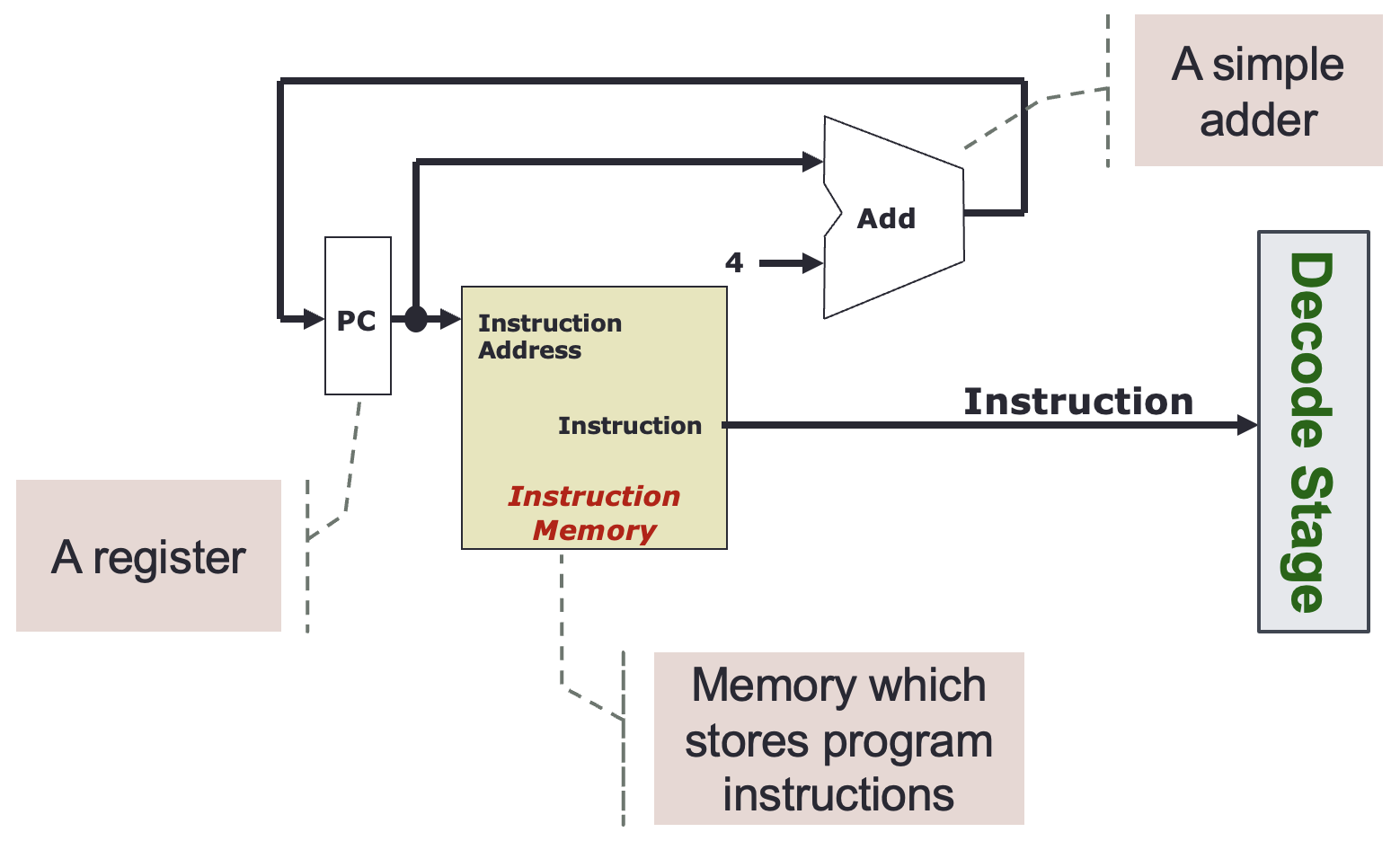
Fetch
- Retrieve Instruction from Main Memory using Program Counter and Instruction Register
MIPS fetch stage
The instruction memory in MIPS is a sequential circuit that only gets updated with the next instruction at the next rising clock edge.
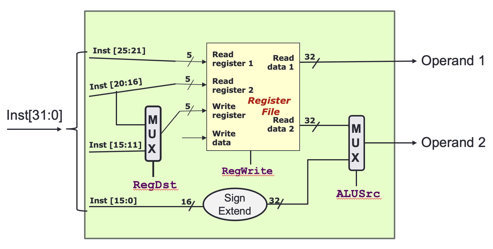
Decode
- Fetch the opcode which is used by the Control Unit to configure the CPU and send the instruction to the ALU. Obtain the operands, which can be either register values or immediate values within the instruction, and send the data to the ALU
MIPS decode stage
Two multiplexers are used to perform the correct operand fetch for R-type and I-type instructions. The bit signal sent to
RegDstis1for R-type and0for I-type. The bit signal sent toALUSrcis0for R-type and1for I-type.
Operand Fetch
- Fetching instruction operand using the corresponding addressing mode
Execute
- Where the execution of Instruction is performed. See MIPS ALU for more information
Memory Access
- Retrieve required data from Main Memory for displacement addressing mode
- See MIPS read data for more information
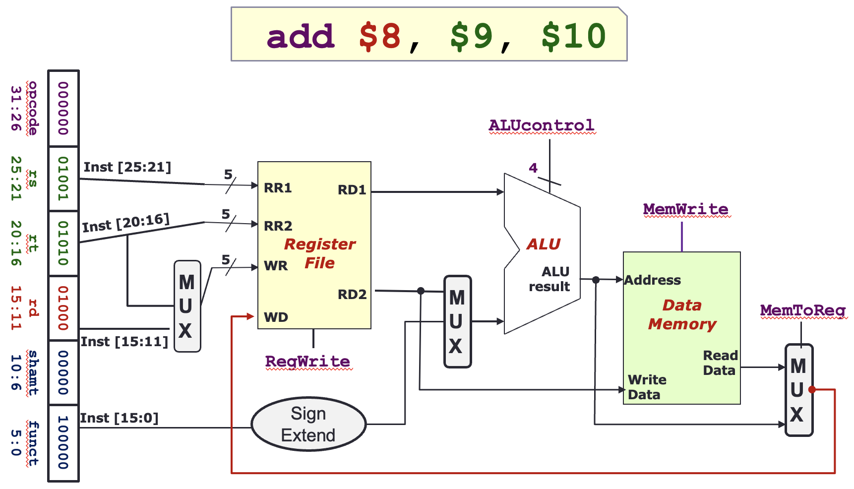
Write Back
- Result is stored back into Main Memory or Register
- See Write Data for more information
MIPS register write back
RegWriteis set to1, so data sent toWDis written to the register atWR.MemToRegis set to1, so theALU resultis sent toWD, instead of theRead Datafrom the MIPS data memory.